
Conclusion: Proper operation of a twin-screw food extruder hinges on three non-negotiable practices: meticulous screw assembly and zone-by-zone temperature control, precise management of feed rate and moisture against screw speed, and disciplined monitoring of torque and die pressure. Unlike single-screw machines, twin-screw extruders demand that operators actively manage the balance between mechanical energy (shear) and thermal energy, because the intermeshing screws generate substantial heat that can degrade food materials if not offset by cooling or feed adjustments. The most common failures—surging output, motor overload, and poor expansion—trace back to feed section instability or worn screw elements rather than the die itself.
1. Pre-Startup Assembly and Inspection
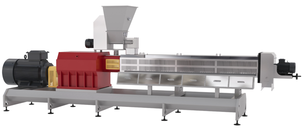
Twin-screw assembly is significantly more demanding than single-screw assembly. The screw configuration—the sequence of conveying elements, kneading blocks, and reverse-flight elements—directly determines mixing intensity, shear levels, and residence time distribution. Before any product runs, lay out all parts systematically and inspect each screw element for nicks, gouges, or hairline cracks. Damaged elements can break apart during operation and cause catastrophic gearbox or barrel damage.
Check all bolts securing the inlet head to the yoke and the clamshell barrel connections. Verify that head support pins are properly seated. Clean the screw shafts with a wire brush and apply anti-seize compound to heated bolts on the die assembly. Elements should slide onto the shafts freely; if resistance is encountered, heat the element gently rather than forcing it, and use a brass-tipped impact tool only as a last resort.
2. Temperature Profile Establishment
The barrel temperature profile is not a single setpoint but a staged progression from feed throat to die. A typical food extrusion profile might run approximately 50–90°C in the first heating zone, rising to 80–120°C in the middle zones, and reaching 90–150°C near the die, depending on the material and target product. However, these figures are starting points, not universal constants.
Two principles govern temperature setting. First, zone 1 should remain cool, often water-cooled with no active heating, to prevent premature melting or sticking at the feed throat, which causes feed bridging and surging. Second, barrel setpoints are not melt temperatures. The actual melt temperature results from the combination of heater input and viscous dissipation from screw rotation. If melt temperature continues rising even after heaters are switched off, the heat is coming from shear, and the remedy lies in screw configuration or screw speed rather than cooling capacity.
Establish a baseline profile by running with a representative formulation, recording all zone temperatures, screw speed, feed rate, and product quality observations. Once acceptable product is achieved, document these conditions as the standard operating procedure for that product.
3. Feed Rate, Moisture, and Screw Speed Coordination
The single most common operational error is treating feed rate and screw speed as independent variables. They are not. In a starve-fed twin-screw extruder, the screws should never be completely filled with material except at the die and in specific kneading sections. Overfilling the screws—by running screw speed too low for the feed rate—produces excessive torque and motor overload trips.
Water injection is equally critical. Typical food extrusion runs at 15–30% moisture by weight in the barrel. Water acts as a plasticizer, reducing melt viscosity and moderating shear heating. Introduce water through injection jets at designated barrel ports, and control the rate precisely. Insufficient moisture leads to high viscosity, excessive mechanical energy input, and poor expansion; excessive moisture dilutes the starch or protein matrix and produces dense, soggy extrudates.
A practical rule: when adjusting output, change one variable at a time. If throughput must increase, raise feed rate and screw speed proportionally while watching torque and die pressure. If torque approaches 80–85% of maximum, stop increasing feed and address the restriction—often a partially blocked die or worn screw elements—before proceeding.
4. Startup Sequence
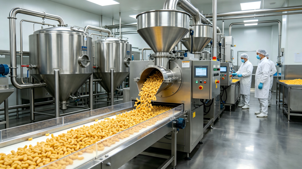
Begin with the die removed or the die open, if the machine design permits. Bring barrel zones to their setpoints and confirm stability. Start screw rotation at a low speed—typically 20–30% of maximum—and begin feeding at a correspondingly low rate. Once material is moving through the barrel and emerging from the die area, install the die and gradually increase screw speed and feed rate together toward the target conditions.
During this ramp-up, watch die pressure and motor torque continuously. A sudden pressure spike may indicate a blocked die hole or a feed surge; reduce feed immediately. Once at target conditions, allow the system to stabilize for several minutes before collecting product for evaluation. Record the time required to reach steady state—this becomes part of the standard operating procedure.
5. Steady-State Monitoring
At steady state, monitor four parameters at regular intervals: melt temperature (not just barrel setpoints), die pressure, motor torque, and product appearance. Die pressure depends on screw speed, feed rate, die open area, moisture content, and melt viscosity; a gradual rise in pressure at constant conditions suggests die wear or partial blockage.
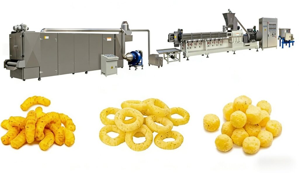
Product quality provides immediate feedback. Poor expansion in puffed snacks or floating feeds typically indicates insufficient pressure and temperature at the die, often from screw wear or low moisture. Unmelted particles or streaks indicate inadequate mixing, which may require higher barrel temperatures, increased backpressure via screens, or a screw configuration change. Burnt specks point to dead zones or excessive residence time in kneading sections.
Surging—variation in die pressure, motor load, or product dimensions—originates in the feed section in roughly 90% of cases. Check for bridging in the hopper, slip-stick in zone 1, or inconsistent feed auger delivery before adjusting downstream parameters.
6. Shutdown and Cleaning
Perform a controlled shutdown rather than an abrupt stop. Reduce screw speed and feed rate together, then stop the feeder and allow the screws to convey remaining material out of the barrel. If the die is to be removed, do so while the barrel is still warm to prevent material from solidifying and seizing the die.
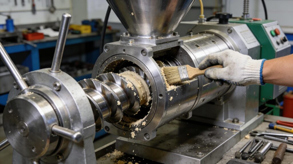
For cleaning, purge the barrel with a suitable purge material—often a coarse meal or dedicated purging compound—while the screws are rotating. Disassemble screw elements only after the barrel has cooled sufficiently to handle safely. Clean elements with a wire brush or soak them in a heated cleaning bath, but never exceed the metallurgical temperature rating of the elements. Inspect keyways and splined bores for wear or cracking before reassembly.

7. Troubleshooting Summary
| Symptom | Most Likely Cause | First Action |
|---|---|---|
| Motor overload trips | Overfilling screws (feed too high for screw speed) | Reduce feed or raise screw speed |
| Surging output | Feed bridging or slip-stick in zone 1 | Cool zone 1, stabilize feed |
| Poor expansion | Screw wear or low moisture | Check screw clearances, verify water rate |
| Melt temperature too high | Excess shear, not heater fault | Reduce screw speed or modify screw configuration |
| Unmelted particles | Low melt temperature or poor mixing | Raise later-zone temperatures, check kneading blocks |
Proper operation of a food twin-screw extruder is ultimately a discipline of observation and incremental adjustment. The machine rewards operators who understand that screw speed, feed rate, moisture, and temperature are coupled variables—and that the die, often blamed for product defects, is rarely the root cause.
 French
 English
 Russian
 Spanish
 Italian
 Arabic
 Portuguese
 German
 Japanese
 Moroccan Arabic
 Persian
 Belarusian