
A twin-screw extruder is a sophisticated piece of processing equipment widely used in the food, feed, polymer, and chemical industries. corn snack extruder It performs multiple unit operations — conveying, mixing, cooking, shearing, and shaping — within a single machine. Understanding its components is essential for proper operation, maintenance, and troubleshooting.

Below is a breakdown of the major components of a typical twin-screw extruder.
1. Feeding System
The feeding system delivers raw materials (powders, granules, or liquids) into the extruder barrel at a controlled and consistent rate.
- Hopper: A storage bin that holds the raw material. Often equipped with a sight glass and level sensors.
- Feeder: Can be volumetric (screw-based) or gravimetric (weight-loss) to ensure accurate and uniform flow.
- Live-bottom or agitator: Prevents bridging or rat-holing of sticky or fine powders.
2. Drive System
The drive system provides rotational power to the twin screws.

- Main motor: Typically an AC or servo motor rated for variable speed control.
- Gearbox: Reduces motor speed while increasing torque, splitting power evenly to the two screw shafts. This is one of the most critical and expensive components.
- Thrust bearing assembly: Absorbs the axial forces generated by melt pressure pushing back against the screws. Without it, screws could damage the gearbox.
- Coupling: Connects the gearbox output shafts to the screw shafts.
3. Barrel Assembly
The barrel encloses the screws and forms the processing chamber. In twin-screw extruders, barrels are usually modular (segmented) and made of wear-resistant bimetallic alloy.
- Barrel segments: Arranged in sections (e.g., 4 to 12 segments) that can be configured differently for various processing zones (feeding, melting, mixing, venting, pressure-building).
- Liner: The inner surface in contact with material; often made of high-hardness alloy (e.g., Ni-hard, powder metallurgy) for wear and corrosion resistance.
- Flanges and bolts: Connect barrel segments securely, allowing for disassembly and reconfiguration.
4. Twin Screws
The screws are the heart of the extruder. They are assembled from individual screw elements (kneading blocks, conveying elements, etc.) on splined shafts.
- Screw shafts: Solid steel rods with splines that carry elements.
- Screw elements: Include conveying elements (forward, reverse, or neutral pitch), kneading blocks, mixing paddles, and restrictive rings. Their arrangement determines shear, residence time, and fill level.
- Direction of rotation: Co-rotating (most common for food/feed) or counter-rotating. Co-rotating screws produce high self-wiping and mixing.
5. Heating and Cooling System
Temperature control is critical for melting and cooking.
- Heaters: Electric resistance heaters (band or cartridge type) wrapped around barrel segments. Some use induction or fluid heating (oil/steam).
- Cooling channels: Integrated into barrel segments for water or oil circulation to prevent overheating or to control specific zone temperatures.
- Temperature sensors (thermocouples or RTDs): Embedded in each barrel zone, providing feedback to the controller.
- Barrel cooling blowers (air-cooled systems): Alternative to liquid cooling, common in smaller lab extruders.
6. Control System
All extruder functions are monitored and adjusted from a control panel.
- Programmable Logic Controller (PLC) or industrial computer.
- Human-Machine Interface (HMI): Touchscreen for setting parameters (screw speed, feed rate, temperature profile, cutters, etc.).
- Sensors: Measure melt pressure, melt temperature, torque, and throughput. Data is used for closed-loop control.
7. Die and Cutter Assembly
The die shapes the extrudate into the final product form.

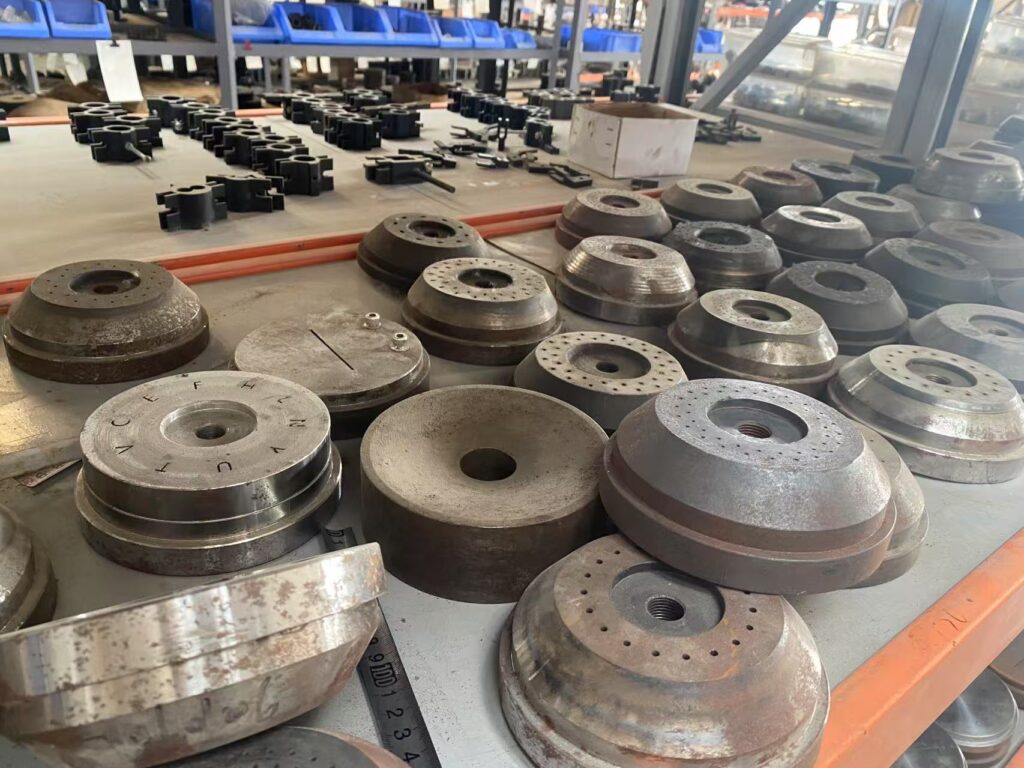
- Die plate or die head: Contains one or more openings (round, ribbon, annular, or custom shapes) that form the product. corn snack extruder Made of hardened stainless steel or tool steel.
- Adapter/transition piece: Connects the last barrel segment to the die.
- Knife assembly (for cut products): A rotating blade that cuts extrudate at the die face into pellets, rings, or other short forms (e.g., floating fish feed, snacks).
- Die heating/cooling: Often has independent temperature control to prevent blockages or surface defects.
8. Ancillary Components (Depending on Application)
8.1. Venting/Vacuum System
- Removes steam, volatiles, or air from the melt.
- Includes a vent port (on a barrel segment), a vacuum pump, and a condenser (to collect evaporated liquids).
8.2. Liquid Injection System
- Injects water, oil, or other liquids directly into the barrel through ports.
- Uses metering pumps and nozzles.
8.3. Enclosure and Safety Guards
- Removable metal covers over the barrel and heating bands protect operators from hot surfaces and moving parts.
- Interlocked with the control system (if guards open, extruder stops automatically).
8.4. Support Base
- A heavy steel frame (skid) that mounts the drive, gearbox, and barrel. Often vibration-damped and anchored to the floor.
Summary Table of Main Components
| Component | Function |
|---|---|
| Feeding system | Delivers material consistently |
| Drive system (motor + gearbox) | Provides torque and speed control |
| Barrel (segmented) | Encloses screws with heating/cooling |
| Twin screws | Convey, mix, shear, and cook material |
| Heating & cooling | Maintains precise temperature profile |
| Control system (PLC/HMI) | Monitors and controls all variables |
| Die and cutter | Shapes and sizes the final product |
| Vacuum/venting | Removes moisture or volatiles |
| Safety guards | Protects operator from hazards |
Final Note

The modular design of twin-screw extruders allows their components to be reconfigured for different products — from breakfast cereals and pet food to bioplastics and engineering polymers. corn snack extruder Regular maintenance of these components, especially screws, barrel liners, and thrust bearings, is essential for long extruder life and consistent product quality.
Always refer to your extruder manufacturer’s manual for component specifications and assembly drawings.