Introduction
The twin-screw extruder is the workhorse of modern polymer, food, and pharmaceutical processing. Unlike single-screw extruders, which rely primarily on friction to convey material, twin-screw extruders use two intermeshing screws to positively displace material from the feed port to the die. This positive displacement principle, combined with a modular design that allows the screw configuration to be customized for specific applications, makes the twin-screw extruder an extraordinarily versatile processing tool.
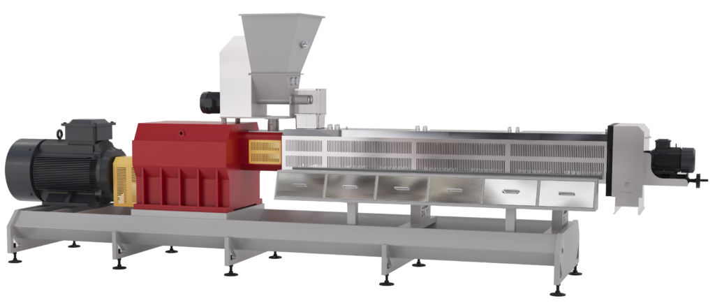
A twin-screw extruder consists of several major systems working in concert: the drive system, the barrel, the screw shafts and elements, the die, and the control system. This article examines each component in turn, explaining its function and how it contributes to the overall extrusion process.
The Drive System
The drive system is the power source that rotates the screws and generates the torque necessary to convey, melt, mix, and pressurize the material. It comprises several key components.
The motor provides the rotational power. In modern twin-screw extruders, DC motors are commonly used, equipped with top-mounted blowers for cooling. A filter removes particles from the cooling air intake to keep the cooling air contaminant-free; if the filter becomes clogged, the motor will automatically shut down to prevent overheating damage.
The gearbox (or reduction gearbox) reduces the motor’s rotational speed to the range required for extrusion while multiplying torque. The gearbox also distributes power to the two screw shafts through a system of gears. In a co-rotating twin-screw extruder, the output shafts rotate in the same direction; in a counter-rotating machine, they rotate in opposite directions.
The torque-limiting coupling sits between the motor and the gearbox. This safety device disengages at a predefined torque limit to protect the motor and gearbox from damage if the screws encounter excessive resistance. If the coupling disengages, the extruder feed systems stop, and the coupling must be rotated in reverse to re-engage.
The Barrel
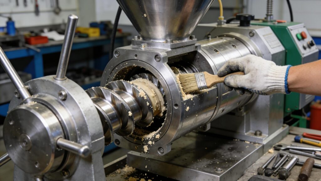
The barrel is the cylindrical housing within which the screws rotate. It is typically constructed as a series of modular sections joined together, allowing the length-to-diameter (L/D) ratio to be tailored to the process requirements. The barrel’s inner surface is precision-machined to closely match the outer diameter of the screws.
Heating and cooling systems are integrated into the barrel. Electrical heater bands or cartridges supply thermal energy to the material, while cooling channels (using water or oil) remove excess heat generated by viscous dissipation. Temperature sensors monitor conditions at multiple points along the barrel, feeding data to the control system. The barrel temperature profile is a critical process parameter: it influences melting behavior, viscosity, and ultimately the quality of the extruded product.
Vent ports may be provided along the barrel length to allow volatiles, moisture, or entrapped air to escape from the melt. These ports are connected to vacuum systems or atmospheric vents, depending on the application. Venting capability is one of the twin-screw extruder’s key advantages, enabling the removal of undesirable components during processing.

The Screw Shafts and Elements
The screws are the heart of the twin-screw extruder. In a modern machine, each screw is not a single continuous piece but rather a segmented assembly built on a central shaft. This modular design is what gives the twin-screw extruder its remarkable flexibility.
The screw shaft (also called the core shaft) is a splined or keyed shaft onto which individual screw elements are mounted. The splines or keyways ensure that the elements rotate with the shaft without slipping. The shaft transmits torque from the gearbox to the elements and must withstand significant torsional and bending stresses during operation.
Screw elements are the individual functional components that perform the actual work of conveying, melting, mixing, and pressurizing. They are available in several basic types:
Conveying Elements
Conveying elements (also called feed screws or transport elements) have a continuous helical flight, similar to a conventional screw. Their primary function is to convey material along the barrel. The pitch of the flight—the axial distance between successive flights—determines the conveying characteristics. A large pitch provides high conveying capacity with relatively low shear, making it suitable for feed and transport zones. A smaller pitch provides greater pressure buildup and more intensive mixing.
Conveying elements can be forward-pitched (right-handed, conveying in the normal downstream direction) or reverse-pitched (left-handed, opposing the flow). Reverse elements create backflow and increase residence time, which can enhance mixing but also increases pressure and energy consumption.
Kneading Blocks
Kneading blocks are the primary mixing elements. Rather than a continuous flight, a kneading block consists of a series of elliptical disks (also called kneading disks or paddles) mounted on the shaft at specific angular offsets. As the screws rotate, the disks of the two screws intermesh, creating intense shear and elongational flow in the gaps between them.
Kneading blocks are used for dispersive mixing—the breaking down of agglomerates and the homogenization of the melt. The intensity of mixing depends on the width of the disks, the stagger angle (the angular offset between successive disks), and the number of disks in the block. A 90° stagger angle provides the most intensive dispersive mixing, while smaller angles provide more distributive mixing.
Mixing Elements
Mixing elements are designed for distributive mixing—the spatial rearrangement of components within the melt without necessarily breaking down particles. They may take the form of slotted screws, pinned screws, or specialized geometries that repeatedly divide and recombine the flow.
Some mixing elements combine forward and reverse flights in a single element. For example, a mixing element may have forward-flight sections interspersed with reverse-flight sections, creating a complex flow pattern that promotes both distributive and dispersive mixing while controlling pressure buildup.
Special Elements
Special elements serve specific functions. Restricting or throttling elements create a localized barrier to flow, increasing pressure and residence time. Shearing elements concentrate high shear in a confined region. Transition elements bridge sections with different flight numbers or profiles.
The flight number (or number of starts) is a fundamental design parameter. Single-flight elements have one helical flight; double-flight elements have two flights spaced 180° apart; triple-flight elements have three flights spaced 120° apart. Higher flight numbers generally provide more uniform conveying and better self-wiping characteristics.
The Die and Downstream Equipment
At the discharge end of the barrel, the die shapes the extrudate as it exits. The die assembly typically includes a breaker plate or screen pack to filter out contaminants and build pressure, followed by the die itself, which contains one or more openings of the desired cross-sectional shape. For pelletizing operations, a cutter with rotating blades slices the extrudate into uniform pellets as it emerges from the die.
The die is a critical component because it creates the pressure required for the extruder to function properly. The pressure drop across the die, combined with the pumping characteristics of the screws, determines the extrusion rate and the degree of fill in the final screw section.

The Control System
Modern twin-screw extruders are equipped with sophisticated control systems that monitor and regulate all key process parameters. The PPC controller (or equivalent PLC-based system) connects to modules for conveying, driving, temperature control, and power supply. An operator panel provides the interface for setting and adjusting parameters, while sensors throughout the machine provide real-time feedback on temperatures, pressures, screw speed, motor load, and other variables.
The control system ensures that the extrusion process remains stable and reproducible. It can automatically adjust heating, cooling, feed rate, and screw speed to maintain the desired conditions, and it can trigger alarms or shutdowns if any parameter exceeds safe limits.
Conclusion
The twin-screw extruder is a complex assembly of interacting components, each with a specific role in the transformation of raw materials into finished products. The drive system provides power; the barrel contains and conditions the process; the segmented screw shafts and elements perform the actual work of conveying, melting, mixing, and pressurizing; the die shapes the product; and the control system orchestrates the entire operation. The modular design of the screw elements is the key to the machine’s versatility: by selecting and arranging conveying, kneading, mixing, and special elements in different sequences, processors can tailor the extruder to an almost limitless range of applications, from polymer compounding to food extrusion to pharmaceutical formulation.
 Spanish
  English
  Russian
  Italian
  Arabic
  Portuguese
  German
  French
  Japanese
  Moroccan Arabic
  Persian
  Belarusian